ENGR 2255 - Lab #6
Title:
- Thevenin and Norton Equivalent Circuits
Objectives:
- Gain experience with Thevenin and Norton Equivalent Circuits
Preparation:
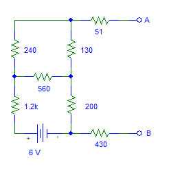
- Determine the Thevenin equivalent circuit for the circuit above.
- Draw the Thevenin equivalent circuit.
- Determine the Norton equivalent circuit.
- Draw the Norton equivalent circuit.
- Pick a load resistor (from standard values) that is close to RTH. Calculate the power absorbed by the load resistor using the circuit above.
- Calculate the power absorbed by the load resistor using the Thevenin equivalent circuit.
- Calculate the power absorbed by the load resistor using the Norton equivalent circuit.
Equipment and Parts:
- Power Supply
- Digital Multimeter(s)
- Resistors: 51 Ω, 130 Ω, 240 Ω, 560 Ω, 200 Ω, 1.2 kΩ, & 430 Ω
Procedure:
- Create the circuit from the preparation on a proto board. Record actual values.
- Measure VOC.
- Measure ISC.
- Determine RTH by computing VOC/ISC.
- Determine RTH by measuring resistance of the circuit. (Note: The voltage source needs to be replaced with a short circuit.)
- Attach to the circuit the load resistor picked in step 5 of the preparation. Measure the voltage across the load resistor and calculate the current through the resistor. Calculate the power absorbed.
- Create the Thevenin equivalent circuit on a proto board. Record actual values.
- Attach the load resistor. Measure the voltage across and current through the resistor. Calculate the power absorbed.
- Create the Norton equivalent circuit on a proto board. Record actual values.
- Attach the load resistor. Measure the voltage across and current through the resistor. Calculate the power absorbed.
Conclusions:
- Compare the predicted values from the preparation with the measured values from the procedure. Indicate how closely the measurements matched the predictions.
- Discuss how well the objectives were met.