ENGR 2255 - Lab #10
Title:
RL Circuits
Objectives:
- Design and test an RL circuit
- Gain further experience using the oscilliscope to analyze time varying circuits
Preparation:
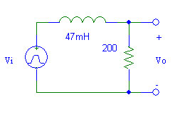
- Calculate the time constant for the RL circuit below.
- Use PSpice to perform a transient analysis of the circuit. Use Probe to plot Vo when Vi is:
- a 0 V to 10 V squarewave with a frequency of 100 Hz.
- a 0 V to 10 V squarewave with a frequency of 1 kHz.
- a 0 V to 10 V squarewave with a frequency of 10 kHz.
Equipment and Parts:
- Prototyping board
- Signal Generator
- Oscilliscope
- Resistor: 200 Ω
- Inductor: 47 mH
Procedure:
- Create the RL circuit from the preparation on a proto board. Record measured resistor value.
- Observe Vo on the oscilliscope with a 0 V to 10 V squarewave input signal of 100 Hz. Draw Vo versus Vi in your lab book.
- Measure the time constant on the oscilliscope.
- Calculate the inductance of the inductor from the time constant and resistance measurements.
- Change the input signal frequency to 1 kHz. Observe and record Vo.
- Repeat for an input signal frequency of 10 kHz.
Conclusions:
- Compare the observed/measured waveforms and time constants with the PSpice simulations. Suggest possible reasons for any discrepancies.
- Discuss how well the objectives were met.