ENGR 2255 - Lab #8
Title:
- Operational Amplifier
Objectives:
- Study the characteristics of the operational amplifier
- Design and test an operational amplifier circuit
Preparation:
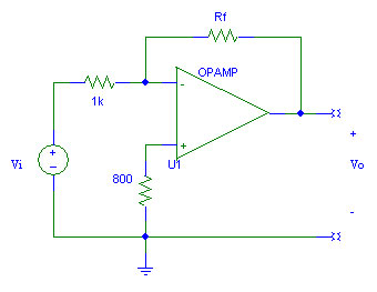
- Determine the value of Rf for which the gain, Vo/Vi, is -5 in the inverting amplifier circuit given above.
- Determine the maximum and minimum values of Vi for which the op-amp will not saturate if the supply voltages are ±15 V.
- Use PSpice to simulate the circuit. Do a DC sweep analysis to create a plot of Vo verses Vi over the range of -15 V to 15 V with 0.5 V increments. (Read about DC Sweep in the PSpice Appendex starting on page A-29.) Set the supply voltages for the op-amp to ±15 V. Use Probe under the Analysis menu to create a plot of Vo and determine the gain from the plot. (If you can't figure this out, move on!)
Equipment and Parts:
- Power Supply
- Digital Multimeter(s)
- Resistors: 800 Ω , 1 kΩ , & ? kΩ
- An LM741C op-amp or equivalent
Procedure:
- Create the inverting amplifier circuit from the preparation on a proto board with supply voltages of ± 15 V. Record actual values.
- Measure Vo for various values of Vi. Use 0.5 V increments starting just below the calculated lower limit in step 2 of the preparation to just above the upper limit.
- Calculate the voltage gain of the circuit in its linear region (non-saturated region) for all appropriate sets of voltages.
- Determine the input resistance of the inverting amplifier circuit as seen by the voltage source. The input resistance is Ri = Vi/Ii. Ii is deteremined by measuring the current through the 1 kΩ series resistor.
- Determine the output resistance of the inverting amplifier circuit. To find the output resistance, the inverting amplifier circuit can be thought of as a Thevenin equivalent circuit consisting of a voltage source with a series resistor (the output resistance). With no load attached, the output voltage will be equal to the source voltage. By attaching a known load resistance, the output voltage is based on a voltage divider between the output resistance and the load resistor. Attach several load resistors and determine the output resistance of the circuit.
Conclusions:
- Compare the predicted values from the preparation with the measured values from the procedure. Indicate how closely the measurements matched the predictions.
- Discuss how well op-amp approaches the ideal op-amp characteristics.
- Discuss how well the objectives were met.