ENGR 2255 - Lab #13
Title:
Sinusoidal Circuits & Phasors
Objectives:
- Analyze a sinusoidal circuit
- Gain further experience using the oscilliscope by measuring phasors
Preparation:
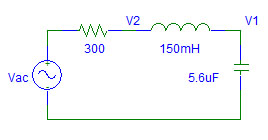
- Determine the impedance of the resistor, the inductor, and the capacitor for a frequency of f = 100 Hz.
- Determine the equivalent impedance, Z.
- If Vac is v(t) = 5 cos (ωt) V, express Vac as a phasor, V.
- Determine the phasor I for the circuit given V and Z.
- What is i(t)?
- Determine V1 and V2 using I and the Z values.
- What are v1(t) and v2(t)?
- Use PSpice to perform a single frequency analysis of the circuit to determine V1 and V2. This is done as an AC Sweep Analysis. Section 10.8 of the text presents AC Analysis Using PSpice.
Equipment and Parts:
- Signal Generator
- Oscilloscope
- Resistors: ~300 Ω
- Capacitor: 5.6 μF
- Inductor: 150 mH
Procedure:
- Measure the internal resistance of the inductor. Choose a resistor so that the total series resistance in the circuit is 300 Ω.
- Create the RLC circuit from the preparation on a proto board.
- Use sine wave generator for Vac. Set the amplitude for 5 V peak. Set the frequency to 100 Hz.
- Measure the amplitude and frequency (by observing the period) of Vac using the oscilloscope. The oscilloscope is generally more accurate than the signal generator. Adjust the amplitude and frequency if necessary.
- Measure the amplitude and phase angle of V1 and V2 using the oscilloscope. The phase angle is found from the time shift relative to Vac. Adjust the time scale to make an accurate measurement.
- Calculate I using the voltage across the resistor, Vac - V2.
Conclusions:
- Compare the theoretical, predicted (simulated), and measured waveforms. If there are significant differences, suggest reasons why.
- Discuss how well the objectives were met.