ENGR 2255 - Lab #11
Title:
RLC Circuits
Objectives:
- Gain further experience using the oscillosope to analyze time varying circuits
- Test second-order circuits
Preparation:
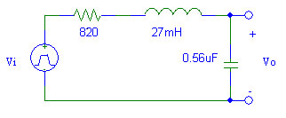
Use PSpice to perform a transient analysis of the circuit. Use Probe to plot Vo. Represent Vi with a constant 5 V source and a switch that closes at t = 0 (sw_tclose). Set the initial condition of both the inductor and the capacitor to 0.
Equipment and Parts:
- Signal Generator
- Oscilloscope
- Resistor: ~820 Ω
- Capacitor: 0.56 μF
- Inductor: 27 mH
Procedure:
- Measure the internal resistance of the inductor. Choose a resistor so that the total series resistance in the circuit is 820 Ω.
- Create the RLC circuit from the preparation on a proto board.
- Use square wave generator for Vi. Set the amplitude for a 5 V step. Set the period to 6 ms (frequency of 166 Hz).
- Observe Vo using the oscilloscope. Draw the waveform in your book.
Conclusions:
- Compare the simulated and measured waveforms. If there are significant differences, suggest reasons why.
- Discuss how well the objectives were met.