ENGR 2255 - Lab #2
Title:
- Kirchhoff's Laws
Objectives:
- Gain experience with Kirchhoff's Current and Voltage Laws
- Gain experience analyzing a resistor network
Preparation:
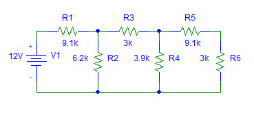
- Determine the equivalent resistance seen by the voltage source.
- Calculate the currents through R3 and R5.
- Calculate the current entering the node connecting R1, R2, and R3 and show that it's sum is zero (by KCL).
- Calculate the voltage across R4 by summing the voltage around the loop containing V1, R1, R3, and R4 and setting it to zero (by KVL).
- Calculate the power absorbed by the resistor network.
Equipment and Parts:
- Power Supply
- Digital Multimeter
- Analog Ammeter
- Resistors: 3 kΩ, 3.9 kΩ, 6.2 kΩ, & 9.1 kΩ
Procedure:
- Create the resistor network from the preparation on a proto board.
- Measure the equivalent resistance with the digital multimeter. Be sure that it is not connected to the voltage source.
- Set the power supply output to 12V. Measure actual output with the multimeter.
- Measure the currents through R3 and R5 using an ammeter.
- Measure the algebraic sum of the currents entering the node connecting R1, R2, and R3.
- Measure the algebraic sum of the currents leaving the node connecting R3, R4, and R5.
- Measure the voltage across R4.
- Measure the algebraic sum of the voltages around the loop containing V1, R1, R3, and R4. Note which you measure as increases and which you measure as decreases (Note: this is determined by the way the voltmeter is attached across each element).
- Determine total power supplied by the voltage source by measuring the voltage and current supplied.
Conclusions:
- Compare the calculations from the preparation with the measurements from the procedure. Indicate how closely the measurements matched the theory.
- Discuss how well the objectives were met.